10. Chapter 7: OTA Update Firmware
It is important to frequently update the firmware of our IoT:bit because the updates may add new features, supply more sensors and actuators, or fix software bugs. In this chapter, you will learn how to update the IoT:bit firmware using OTA and develop a corresponding program. OTA (Over-the-air) is a technology that allows devices to obtain firmware or operating system updates via Wi-Fi or mobile broadband. Through OTA, you do not need to connect the IoT:bit to a computer over USB to perform updates.
10.1. How to judge if the current IoT:bit supports OTA?
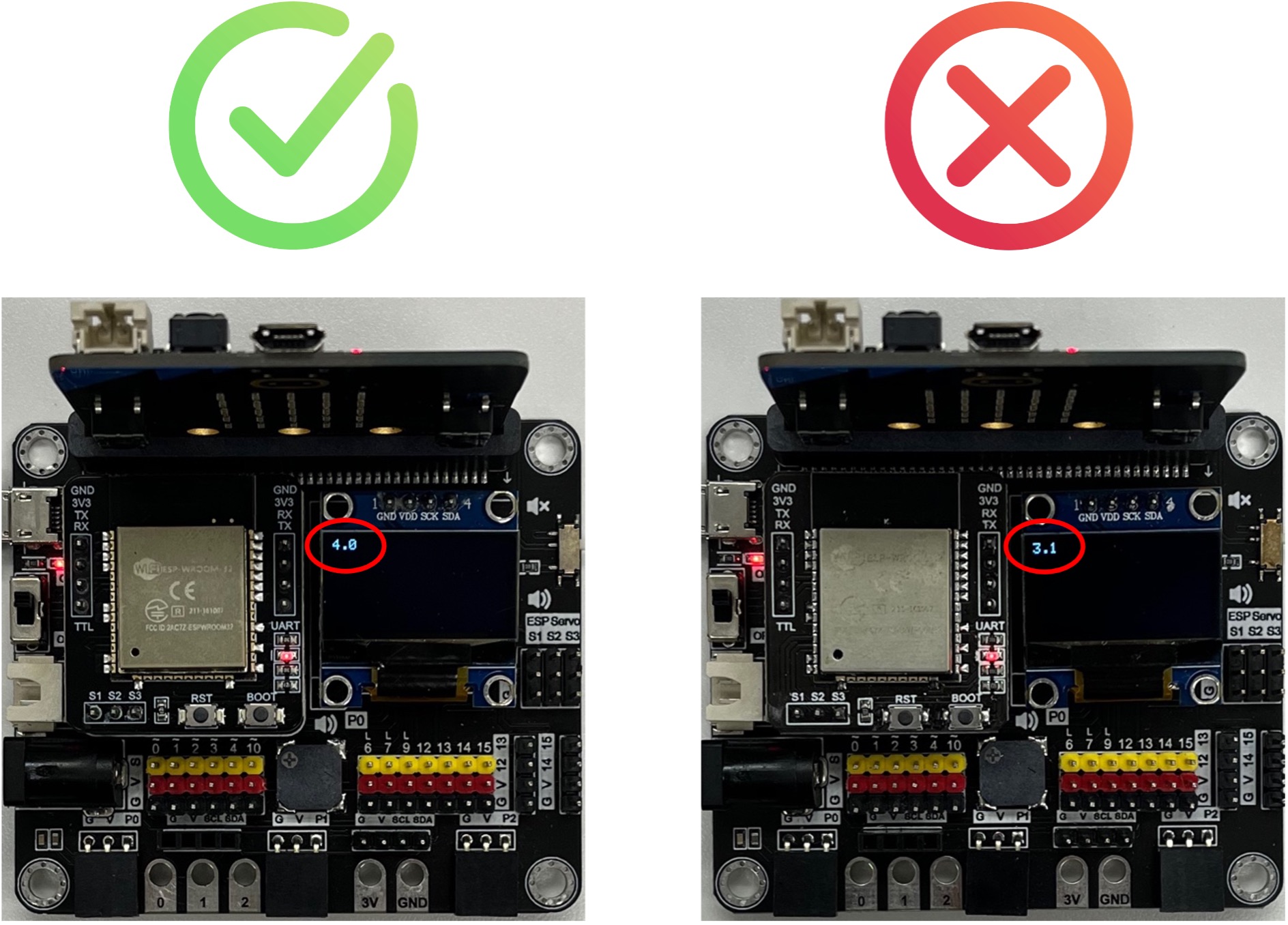
OTA functionality is only available in firmware version 4.0 or above. You can download this makecode program to your micro:bit, the version number will be displayed on start. If the version is lower than 4.0, you need to use USB TTL to update firmware (section 10.6).
If you prefer not to update the firmware yourself, you can: 1) purchase a new iot:bit, which comes with the latest firmware pre-installed. 2) contact us for assistance with updating the firmware. Please note that you’ll need to ship the device to us, and a shipping fee will apply.
10.2. Programming (Makecode)
Goal:
Develop a program to obtain updates via OTA.
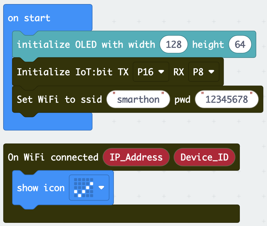
Step 1:Connect WiFi
Before we download the updates via OTA, we need to connect to the network. We have already know how to connect to the WiFi in the first chapter.
Step 2: Setup a function to show the current version
Snap a
on button A pressedto stageGo to IoT:bit -> ESP and find
firmware versionDraw the firmware version variable to a
show string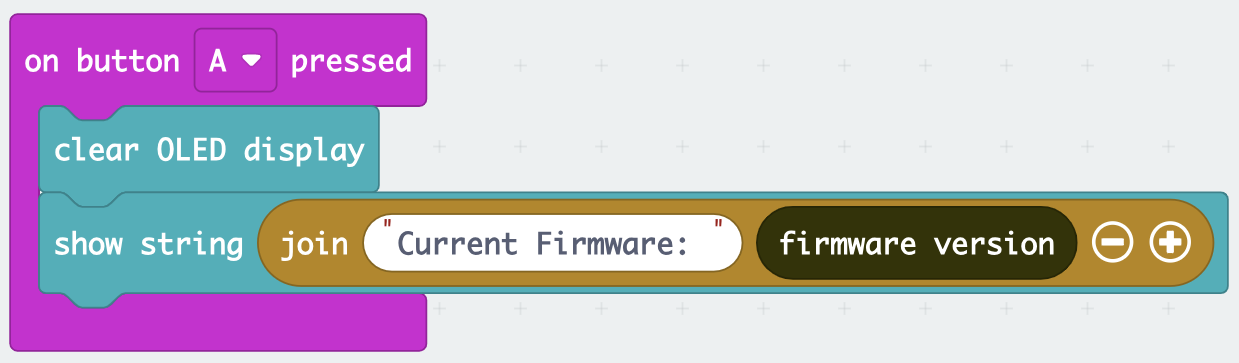
Step 3: Setup a function to start the OTA update
Snap a
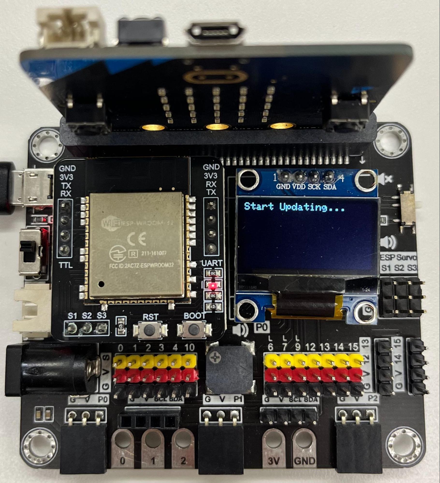
on button B pressedto stageShow a message on the OLED to indicate that the OTA update has started
Go to IoT:bit -> ESP and snap the
Update Firmware to Latest Version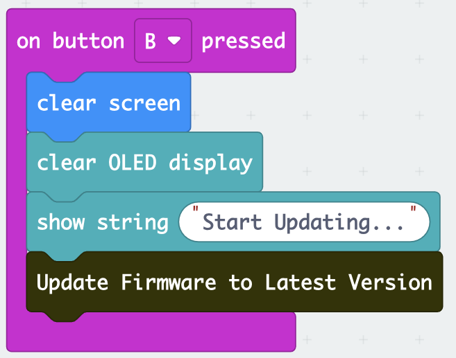
Step 4: Setup a OTA update progressing listener
Snap the listener
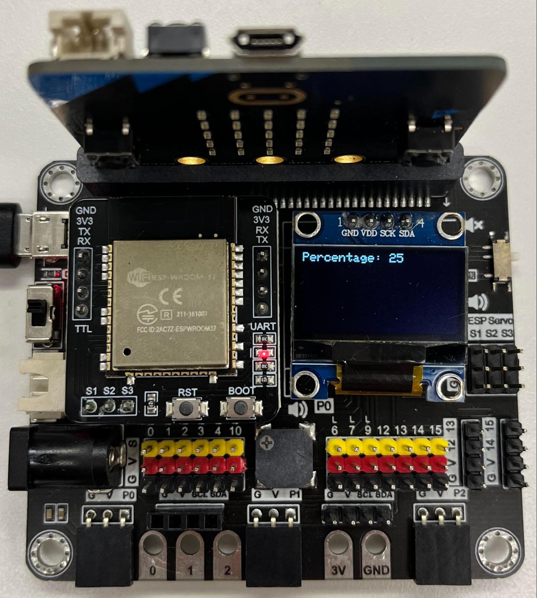
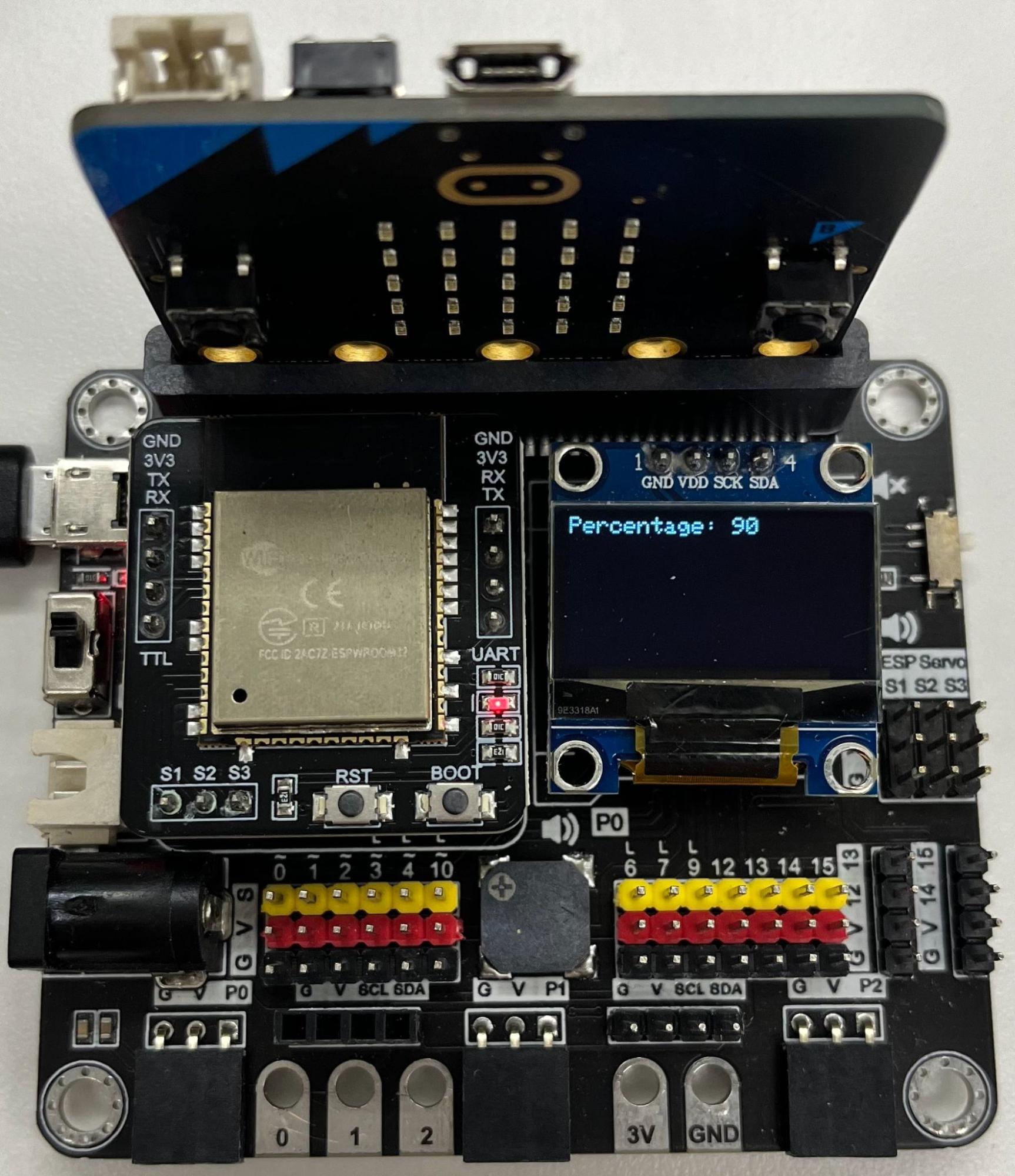
OTA Progressfrom IoT:bit -> ESP to stageDraw the
PercentageValuefromOTA Progressto theshow stringto display the process percentage
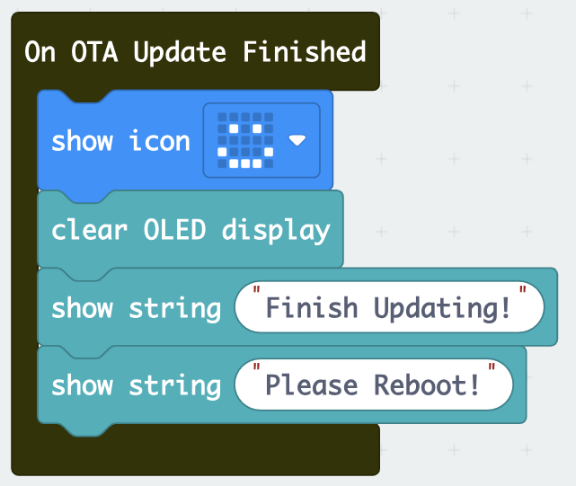
Step 5: Setup a OTA update finish listener
Snap the listener
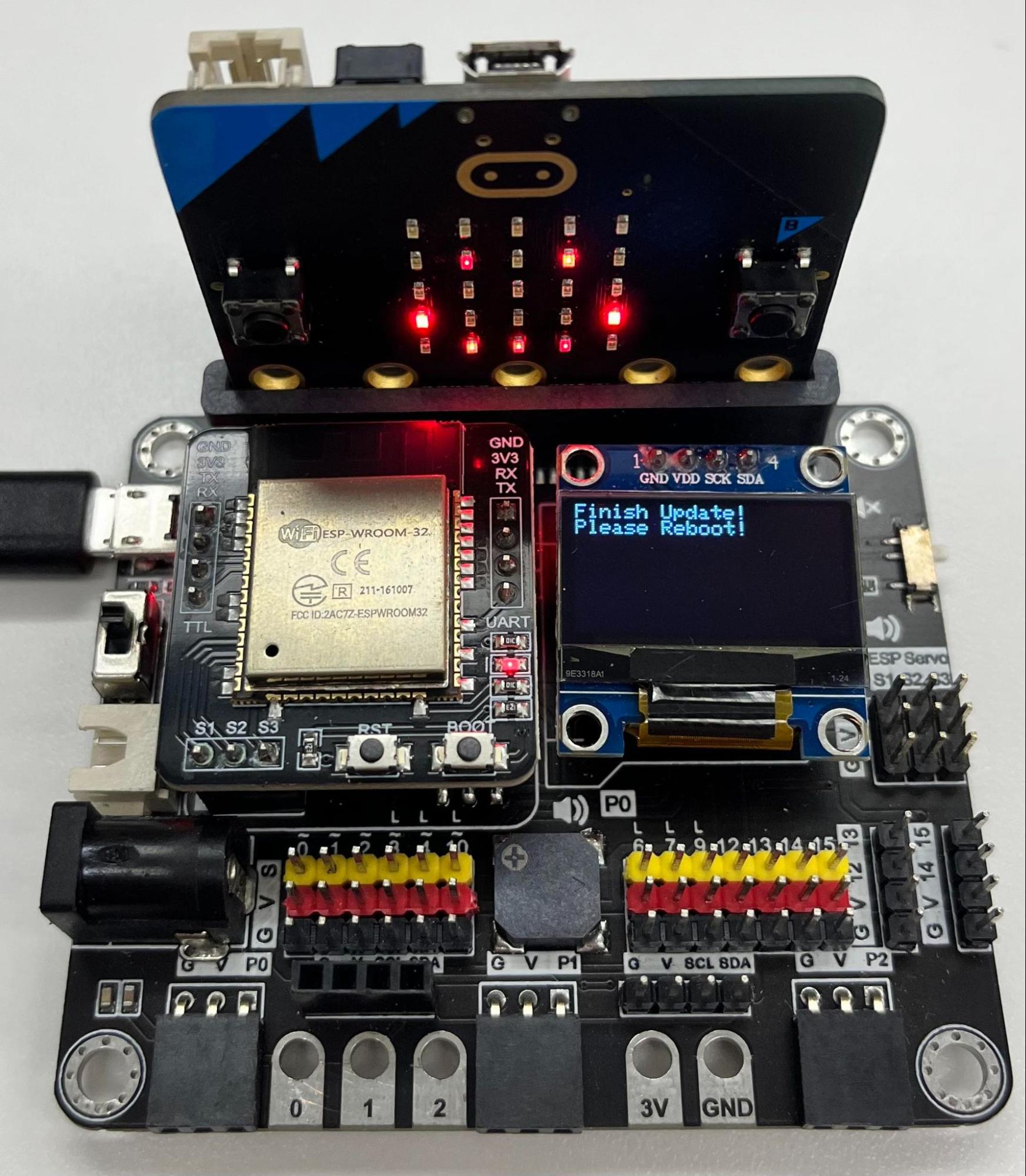
On OTA Update Finishedfrom IoT:bit -> ESP to stageShow an icon and a message on the OLED to indicate that the OTA update has finished.
Show another message to remind you to reboot
Step 6: Setup a OTA update failed listener
Snap the listener
On OTA Update Failedfrom IoT:bit -> ESP to stageDraw the
MessagefromOn OTA Update Failedto theshow stringto show the error message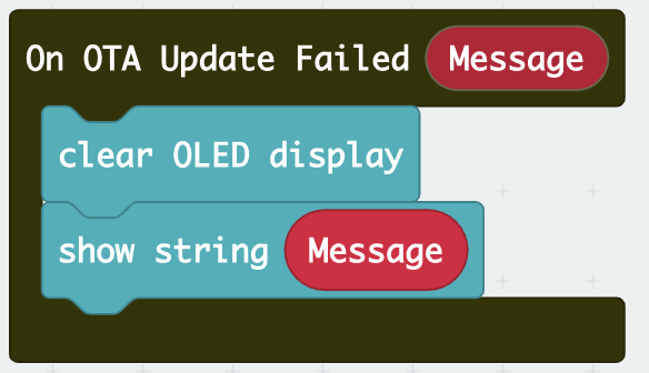
Full Solution
MakeCode: https://makecode.microbit.org/_EFiAdMEmvFqD
You could also download the program from the following website:
10.3. OTA Update
Goal:
Update the firmware using the program above.
Step 1: Before start
Download the program into Micro:bit
Find a place with a strong and stable WiFi connection
Turn on IoT:bit and wait for the icon “tick” showing (Wifi connected)
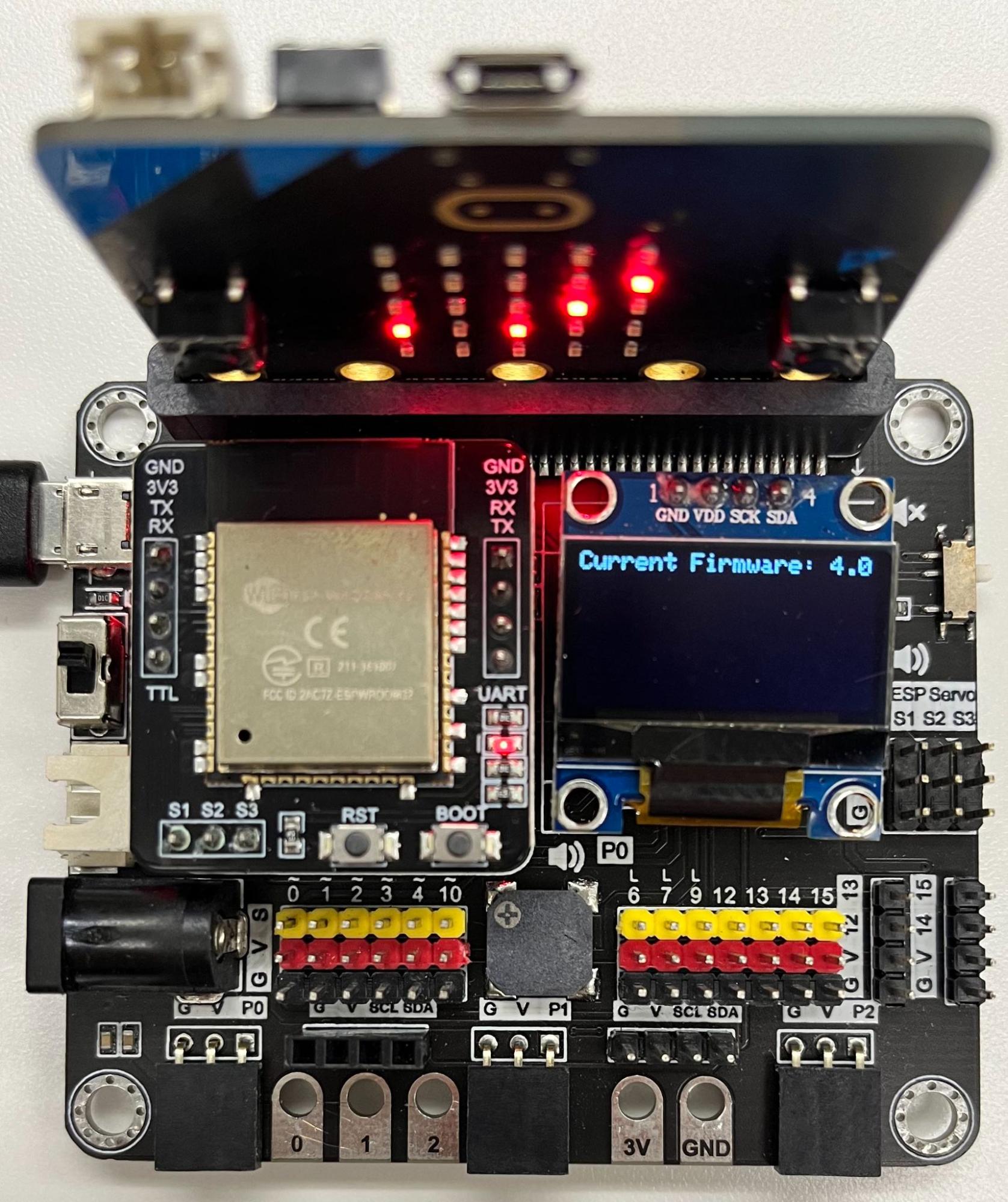
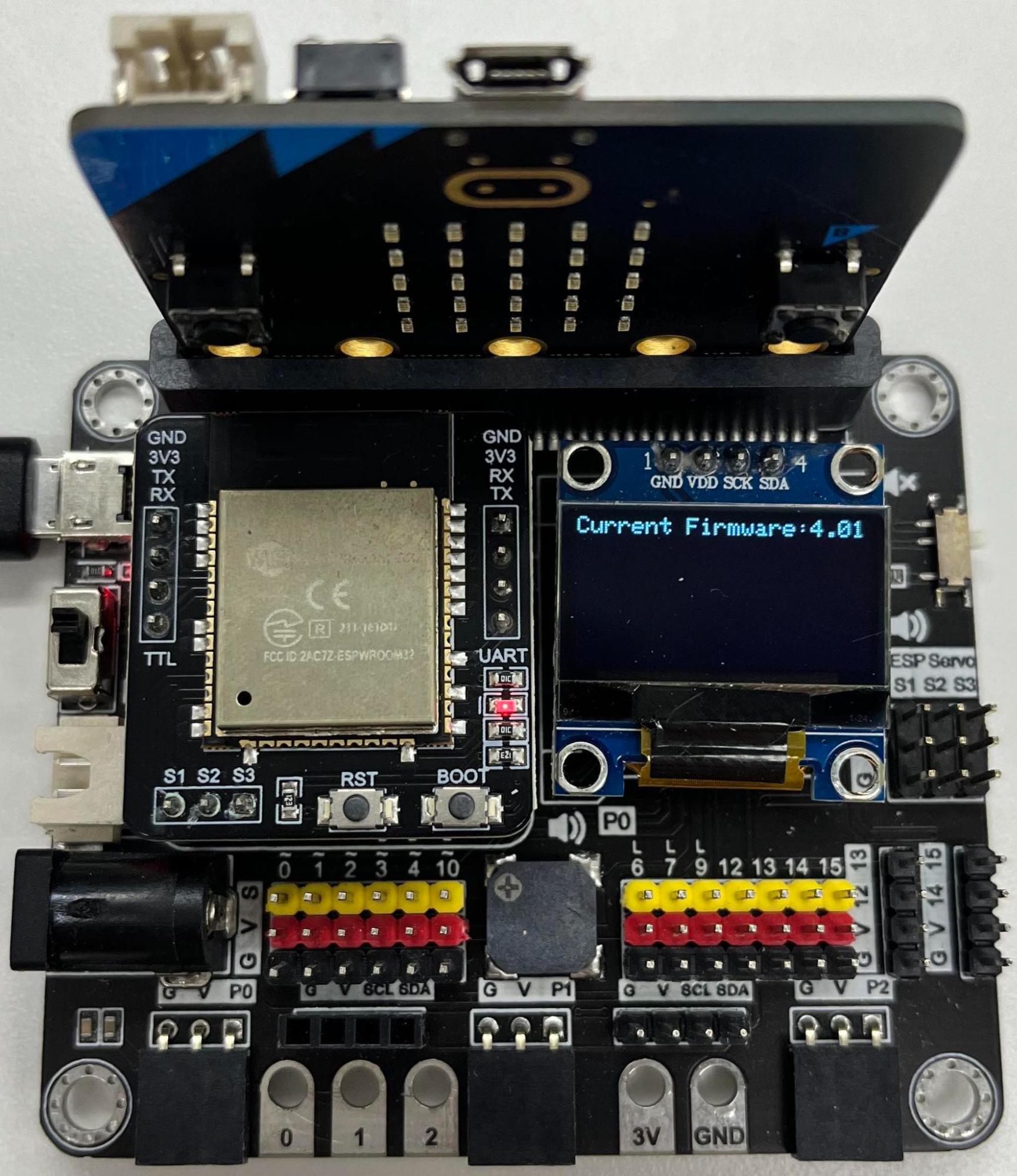
Step 2: Check current version
Press A to display the current firmware version
Step 3: Start OTA update
Press B to start OTA update
Check if the update is ongoing (Percentage from 0 to 100)
Do not disconnect from power / Wifi during the update process unless necessary
Step 4: Update completed
The micro:bit LED shows a smiley face, which means the OTA update is complete
Reboot the IoT:bit by turning off and on the power
Step 5: Check latest current firmware version
Press A again to check the current firmware version
Finished!
10.4. Troubleshooting on OTA Update
If any error message appears, please follow the instructions below and DO NOT turn off the power.
NETWORK_NOT_STABLE — Press B to retry. If this error message persists, please connect a more stable WiFi and try again.
FILE_NOT_EXIST – Please contact Smarthon
When updating firmware, please note:
Do not turn off IoT:bit and micro:bit when updating
If the update is not progressing for more than 10 minutes, you can reboot IoT:bit and try again
Make sure the WiFi network signal is stable and in good condition
Once the firmware update has started, do not execute the update function again ( do not press the button B again) unless any error message is display on the OLED
10.5. Firmware Release Notes
Available for ESP32
Version 4.3 — 16 Aug 2025 (Latest version)
Add the Blynk support for both write and read
http fix for post “” body handling
Download: firmware_v4.3
Version 4.2 — 30 Aug 2024
Features:
Add the IFTTT webhooks equivalent function
Download: firmware_v4.2
Version 4.01 — 12 Jun 2023
Features:
Add the ledc module back
Fixes:
Fix the issue that cannot control servo
Download: firmware_v4.01
Version 4.0 — 5 Mar 2023
Features:
Add OTA function API to allow user download the latest/specific version of firmware
Version 3.2
Features:
Add HTTP function API to allow the HTTP GET request
Version 3.1 — 17 Dec 2020
Features:
Add NTP function API to allow user set the Time Zone
Fixes:
Fix HTTP connection (include HTTP, IFTTT, Thingspeak, WAN/Channel Control) crash issue when received ERROR Code
Version 3.0
Features:
Massive modified of the Serial Table return
Compatible to latest version PXT (v0.5+)
Version 2.3
General:
Update the http result wording
Update the Wifi connection wording
Version 2.2
Features:
Update the ESP Servo AT command, now allow to control the three Servo ports by one command
Version 2.1
Features:
Add network status flag
Add NTP function
Fixes:
Fix the Wifi AP/hotspot mode for esp32
Fix the bug when using esp32 to perform pwm and servo control
General:
Renew the wordings
Change the pubnub connection URL to smarthon domain address
Version 2.0
Features:
Introduce network connection status
Update to compatible with esp32
10.6. Wired Firmware Update
For IoT:bit firmware versions lower than 4.0, please update according to this tutorial.
Things you need
A computer with Windows OS
4 jumpers wires (female-to-female)
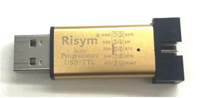
USB TTL (You can buy it here or other Taobao stores)
Step 1: Install CP210x driver
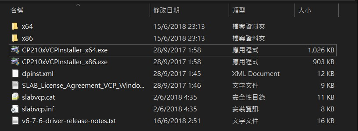
Download and extract “CP210x Windows Drivers” from Silicon Labs website
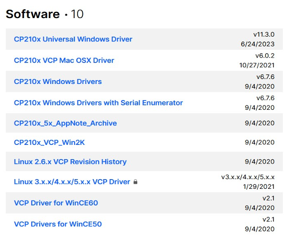
In the extracted folder, execute “CP210xVCPInstaller_x64.exe” to install the CP210x driver
Step 2: Obtain Flash Download Tools
Download and extract “Flash Download Tools” from ESP website
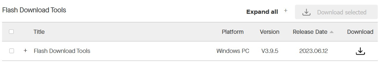
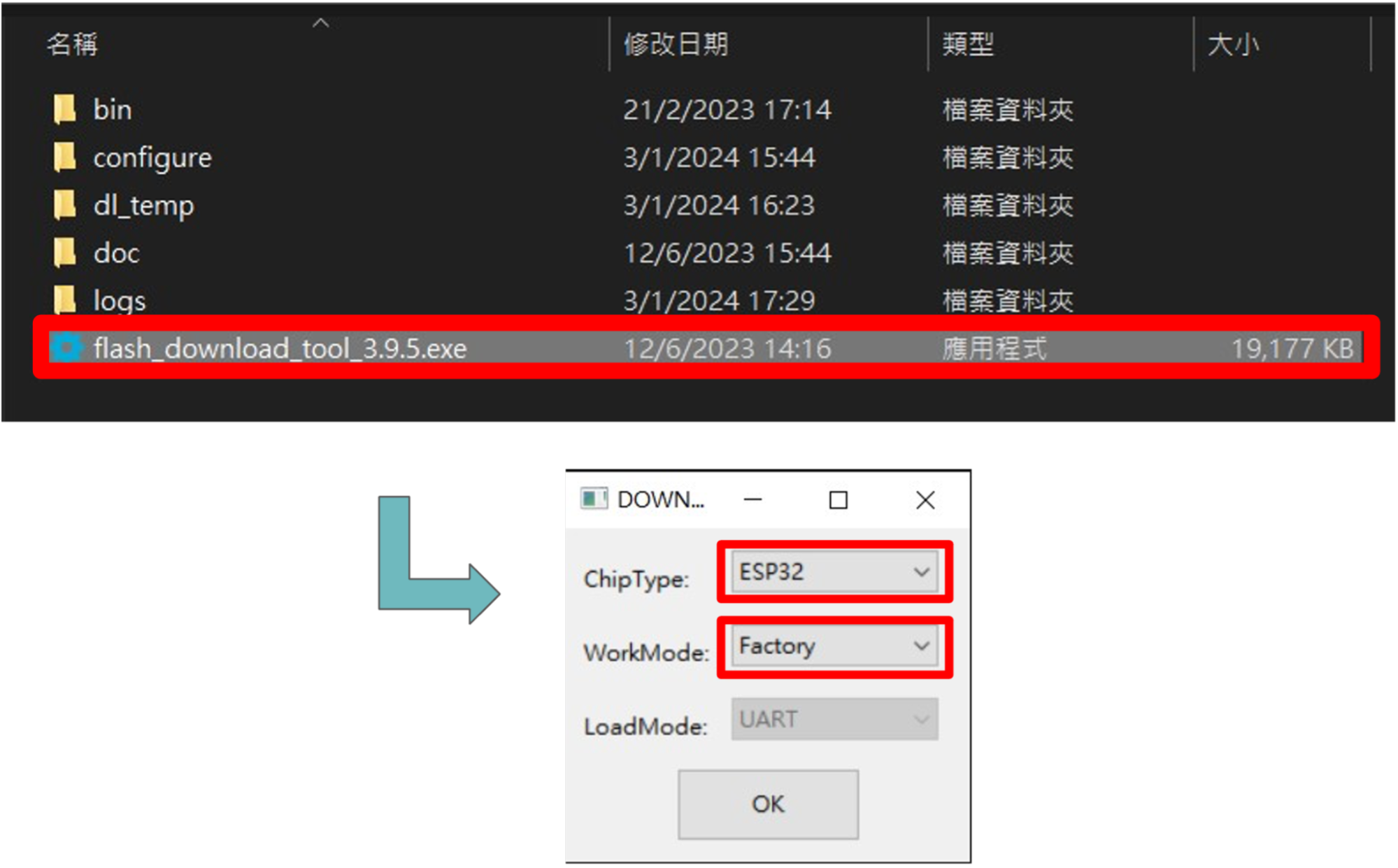
Execute Flash Download Tools
Change the settings to ESP32 and Factory, then press OK
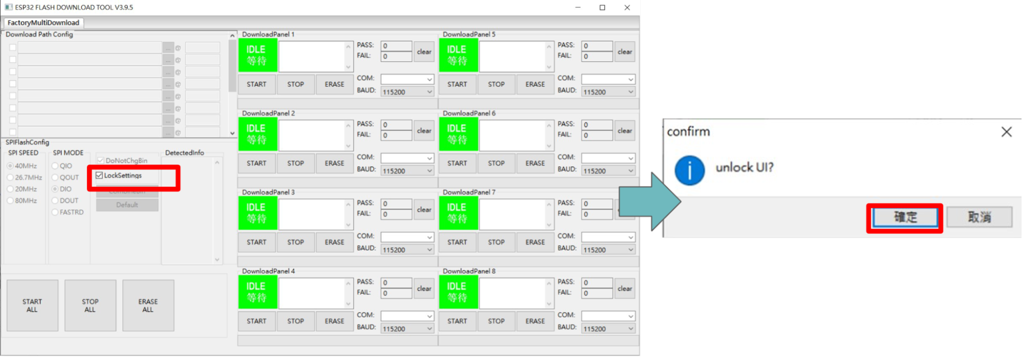
Uncheck “LockSettings” on SPIFlashConfig and click OK
Step 3: Connect ESP32 to computer
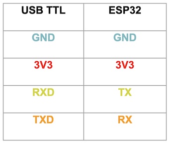
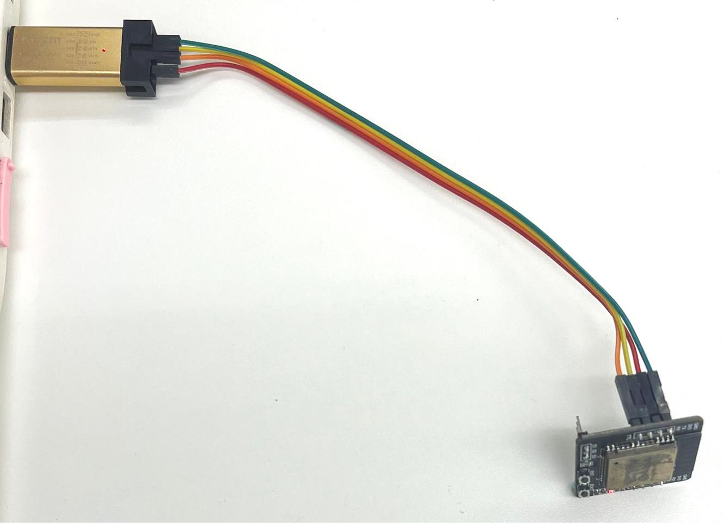
Follow the pictures and mapping table below to connect ESP32 and USB TTL
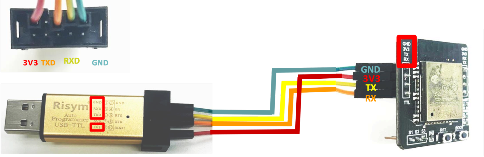
Plug the USB TTL into computer USB port
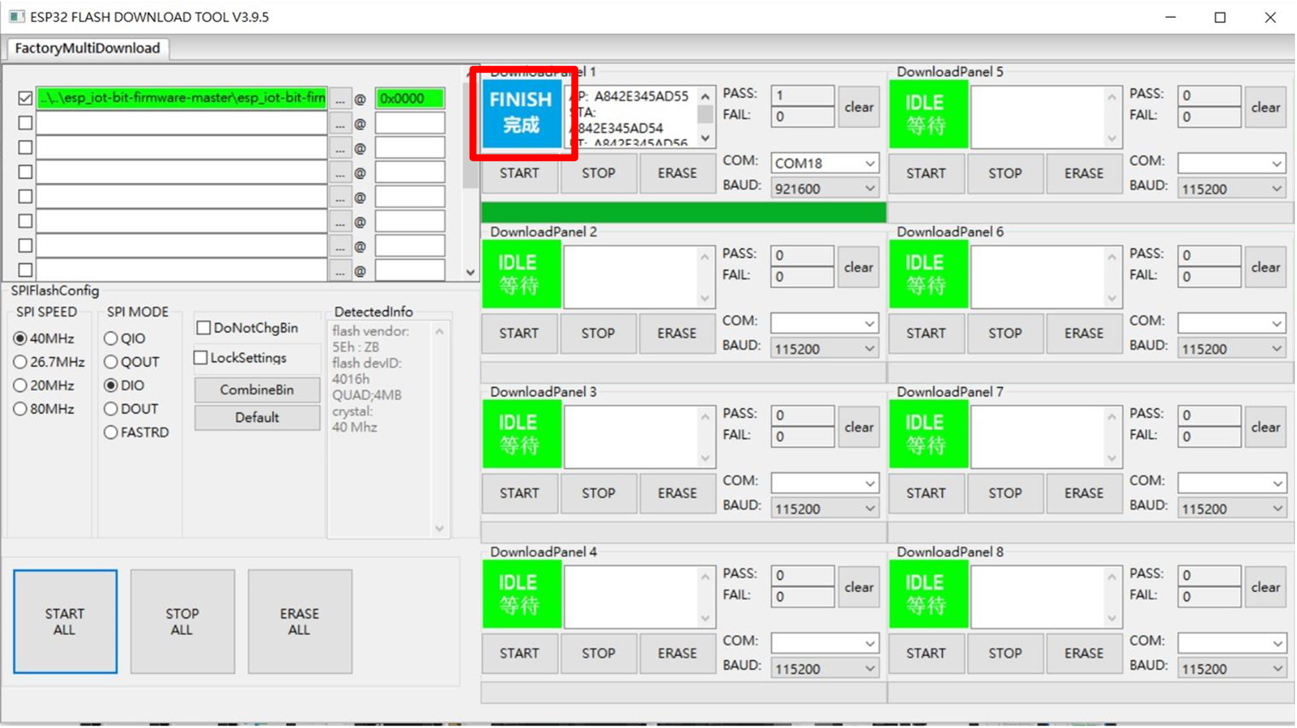
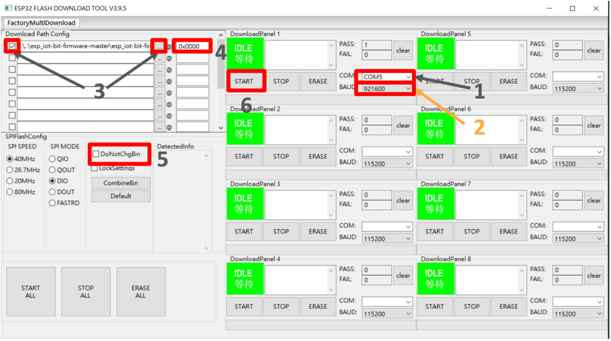
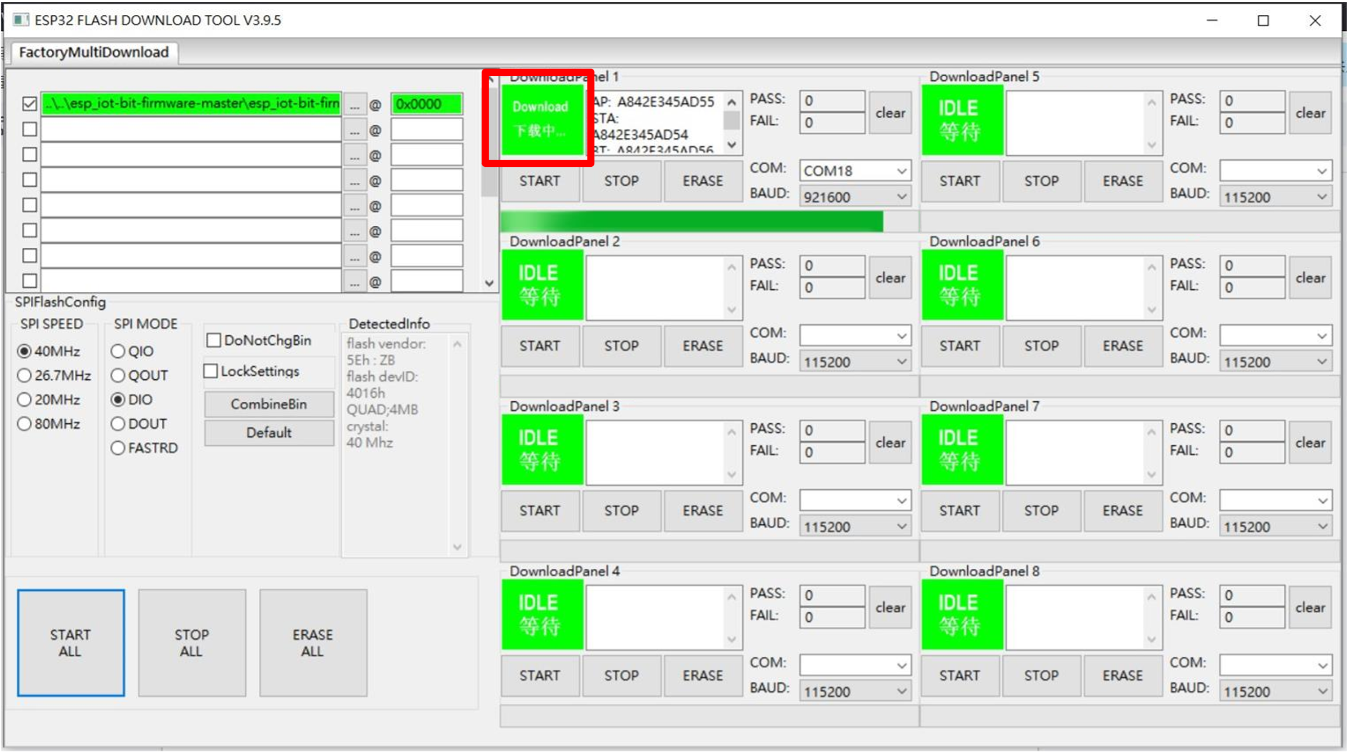
Step 4: Flash Download Tools burn setting
Select the serial port at COM
Select 921600 at BAUD
Select the IoT:bit firmware Bin file and check the nearby box
Enter the burning address 0x0000
Uncheck DoNotChgBin
Do not change other settings, click START to start burning
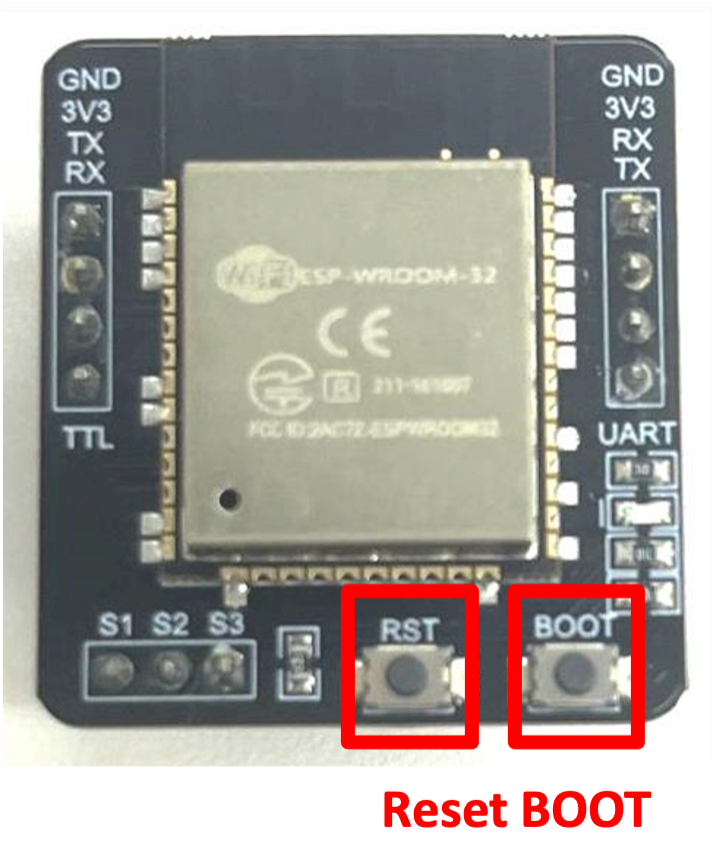
Step 5: After pressing START, put ESP32 into burning mode
Hold the BOOT button
Press and release the RST button
Release the BOOT button
Step 6: Wait for the burning to complete
Step 7: Burning completed