17. Scenario Example 3 : Transport safety and security
Level: 
17.1. Introduction
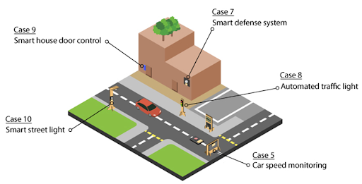
Transport safety and security is the primary concern of a city. Car speed and traffic conditions are being monitored in the public transportation system. Only the responsible person of the corporation can enter the building, alerts will be sent on the network if there are suspicious people nearby. This Scenario is the integration of these five functions:
Car speed monitoring (Case 5)
Automated Traffic Light (Case 8)
Smart Street Light (Case 10)
Smart defense system (Case 7)
Smart House door control (Case 9)
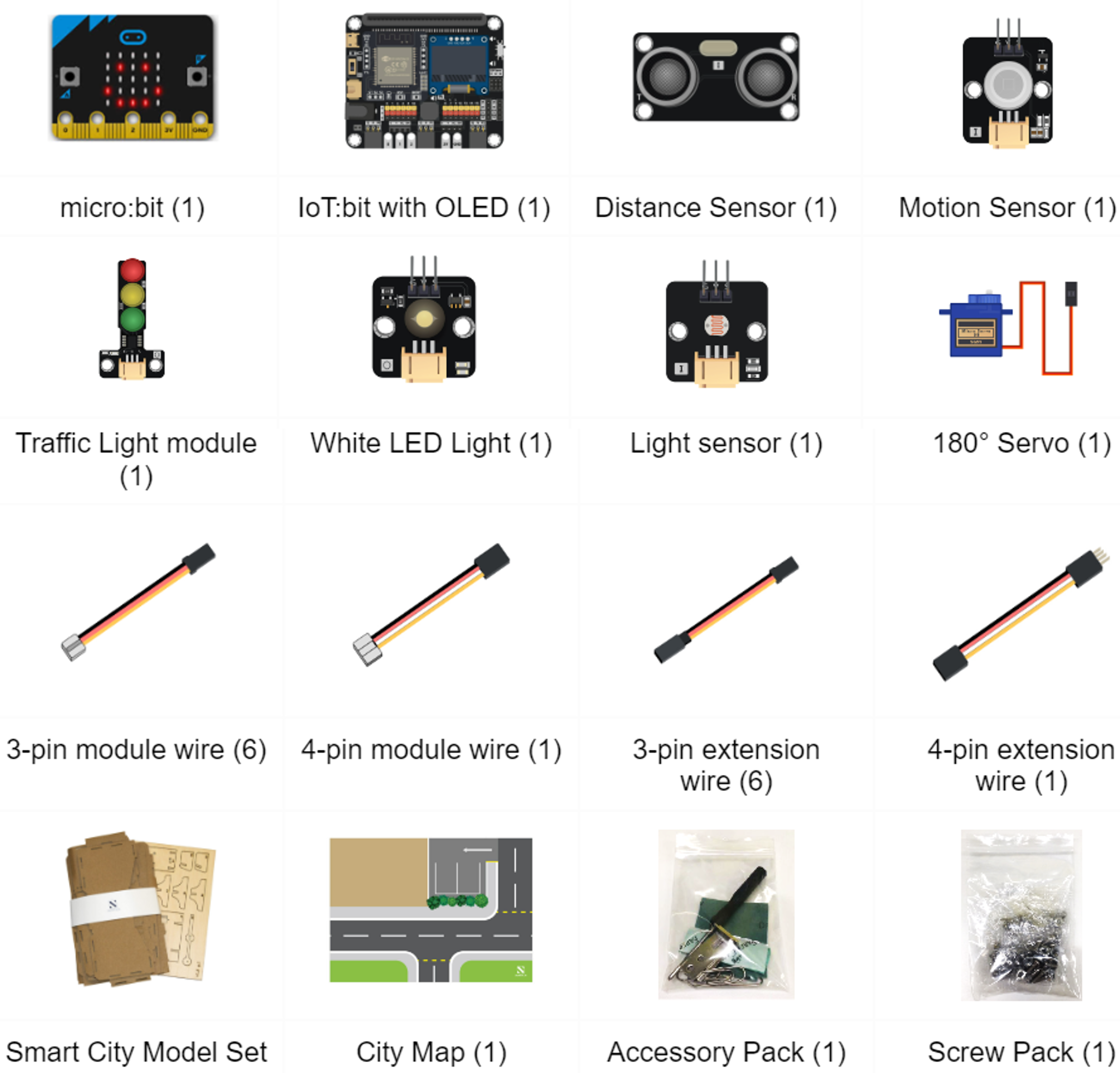
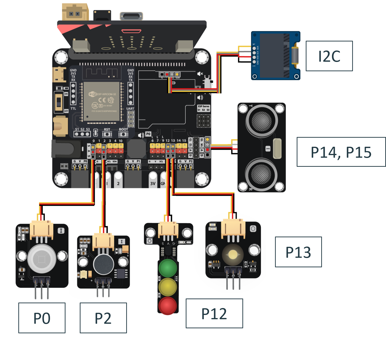
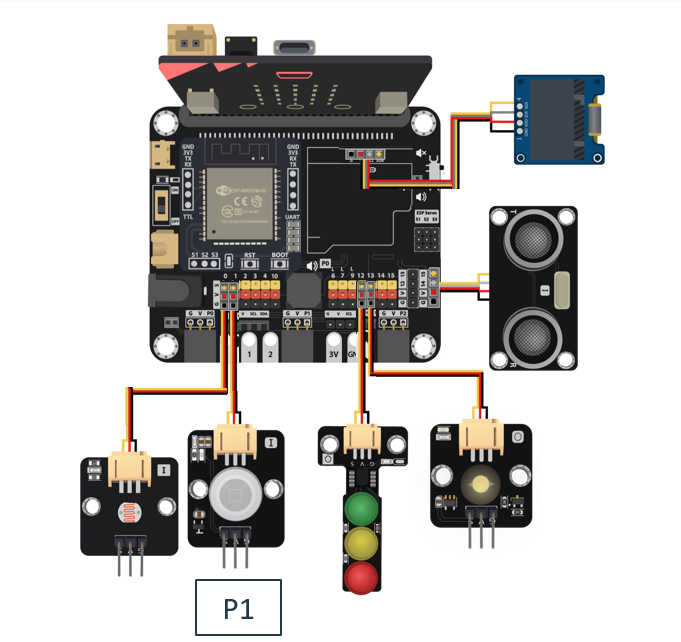
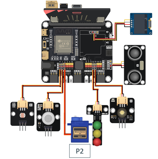
17.5. Hardware connect
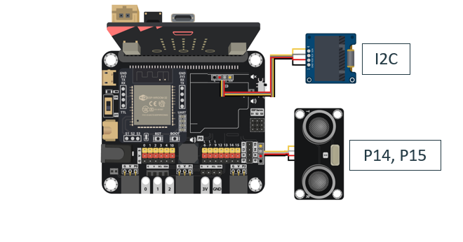
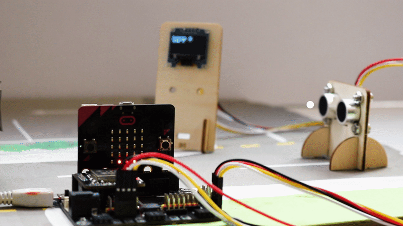
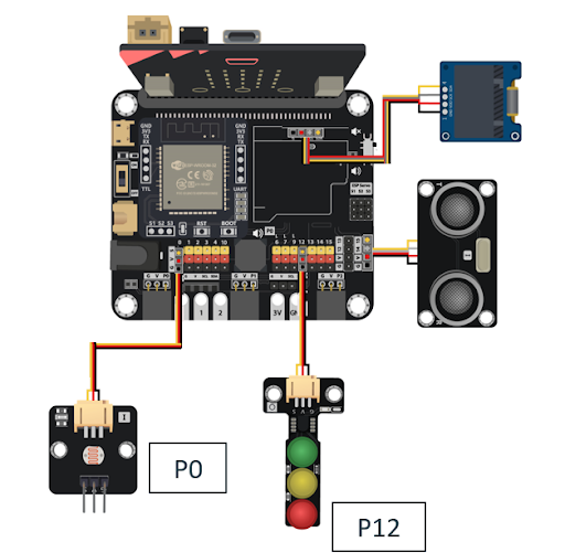
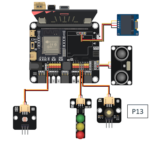
Connect the Distance Sensor to P14 (trig)/ P15 (echo) port of IoT:bit.
Extend the connection of OLED to the I2C connection port of IoT:bit.
Connect the Light Sensor to P0 port of IoT:bit.
Connect the Traffic LED Module to P12 port of IoT:bit.
Connect the white LED Light to P13 port of IoT:bit.
Connect the Motion Sensor to P1 port of IoT:bit.
Connect the 180ᵒ Servo to P2 port of IoT:bit.
17.6. Programming (MakeCode):
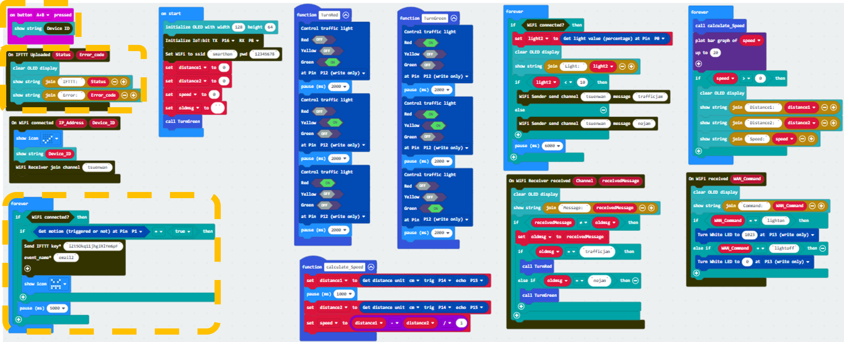
Scenario 3 Full Solution
MakeCode: https://makecode.microbit.org/16876-57308-88647-06271
You could also download the program from the following website:
17.7. Step By Step Tutorial
17.7.1. Part 1: Setting up the Car speed monitoring (Case 5 Revised)
1.1 Hardware Connect
Connect the Distance Sensor to P14 (trig)/ P15 (echo) port of IoT:bit.
Extend the connection of OLED to the I2C connection port of IoT:bit.
1.2 Programming (MakeCode)
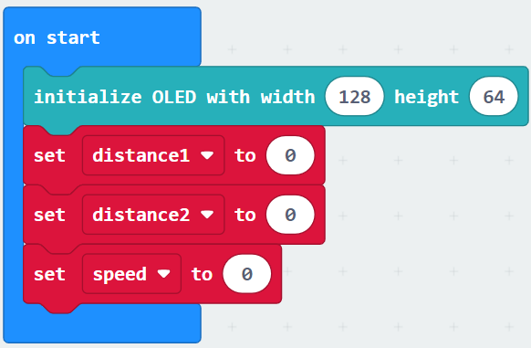
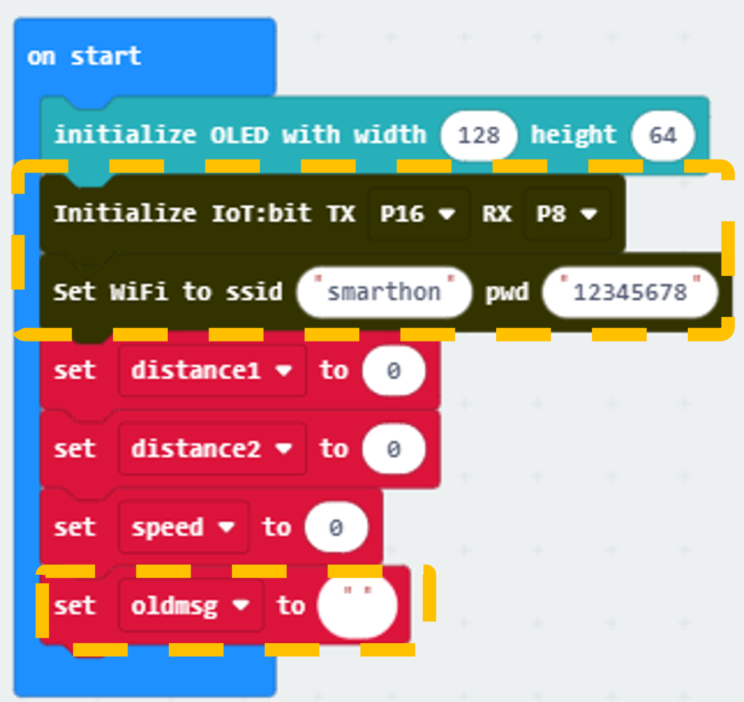
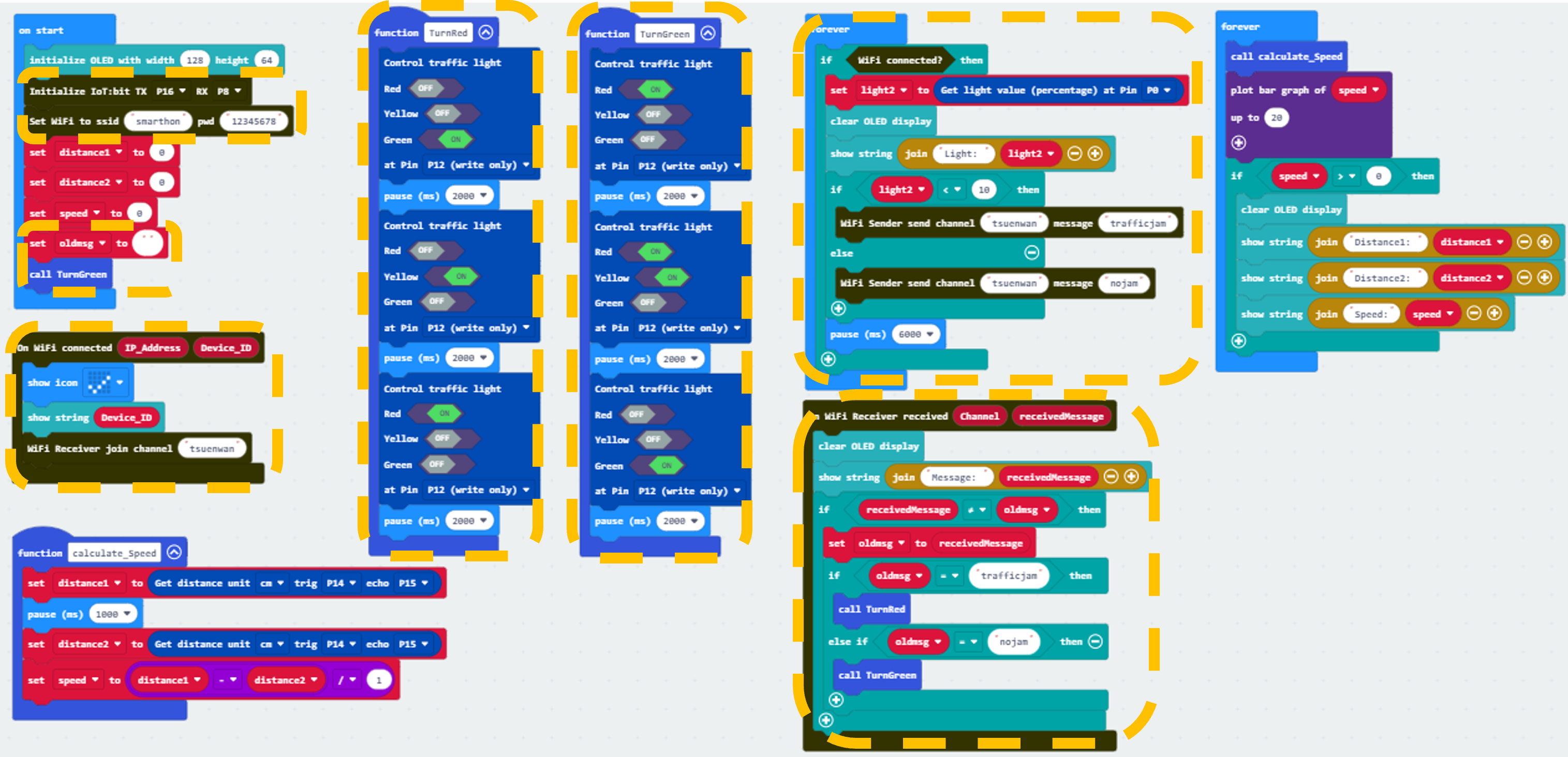
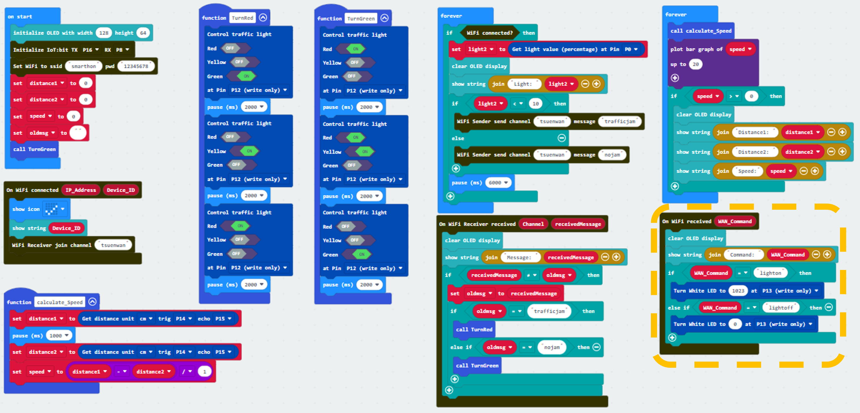
Step 1. Initialize OLED screen
Drag Initialize OLED with width:128, height: 64 to on start.
Set distance1, distance2 and speed to 0 from variables.
Step 2. Set up function (calculate_Speed)
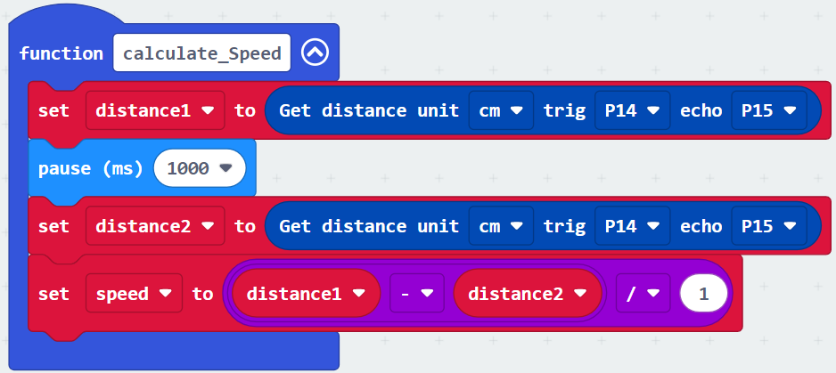
Set up a new function calculate_Speed from Advanced > Functions.
Set distance1 to get distance unit cm trig P14 echo P15 (distance from the car to the distance sensor before 1 second) Drag Pause to wait 1000ms and set distance2 to get distance unit cm trig P14 echo P15 (distance from the car to the distance sensor after 1 second).
By the equation of speed = distance / time. We get the speed of the moving car to (distance1-distance2)/1 (unit: cm/s).
Step 3. Calculate car speed
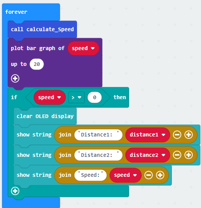
In block forever, call function calculate_Speed from Advanced > Functions to get the speed of the moving car.
Snap If statement into the loop.
Plot bar graph of … from Led and draw variable speed into the plotted value. Set value up to 20.
In if speed ≥0, snap clear OLED display from OLED to avoid overlap.
Snap show string and show value of variables distance1, distance2 and speed.
Part 1 Solution:
MakeCode: https://makecode.microbit.org/S08334-56214-27815-93357
You could also download the program from the following website:
Part 1 Result
It will keep checking the distance of cars from distance sensor by distance sensor in every 1s. The speed of the cars will be shown on OLED. A bar chart of speed will be shown on micro:bit LED also.
17.7.2. Part 2: Setting up the Automated Traffic Light (Case 8 Revised)
2.1 Hardware Connect
Connect the Light Sensor to P0 port of IoT:bit.
Connect the Traffic LED Module to P12 port of IoT:bit.
2.2 Programming (MakeCode)
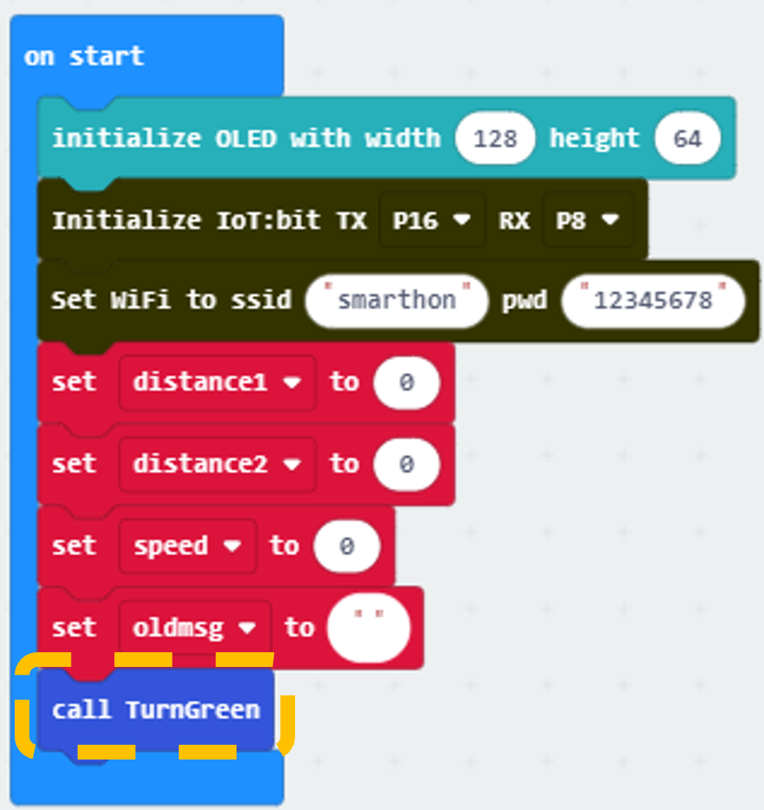
Step 1. Connect to WiFi
Snap Initialize IoT:bit TX P16 RX P8 from IoT:bit to on start.
Snap Set Wi-Fi to ssid pwd from IoT:bit.
Enter your Wi-Fi name and password.
Set variable oldmsg to “” from variables.
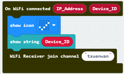
Step 2. Show icon “tick” and join channel after WiFi connection
Snap show icon from basic to On WiFi connected and select icon tick.
Snap show string Device_ID.
Snap WiFi Receiver join channel from IoT:bit > channel.
Set channel to tsuenwan.
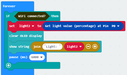
Step 3. Check traffic status
Snap if statement to block forever
If WiFi is connected,
Create a new variable light2 and set light2 to light value from light sensor at P0.
Snap clear OLED display from OLED to avoid overlap.
Snap show string and show value of variables light2.
Pause 6000 (ms) to another checking.
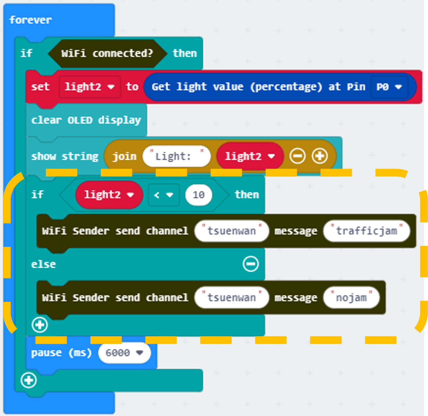
Step 4. Send notification when someone pass by
Snap if statement
Set light2 < 10 in to if-condition (traffic jam is detected)
Snap WiFi Sender send channel… message… from IoT:bit > channel
Set channel to tsuenwan, message trafficjam
Set else-condition (traffic jam is not detected)
Snap WiFi Sender send channel… message… from IoT:bit > channel
Set channel to tsuenwan, message nojam
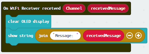
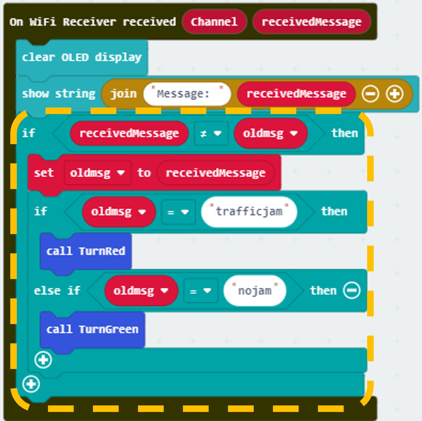
Step 5. Receive WiFi message
Snap On WiFi Receiver received.
Go to OLED, snap the clear OLED display to On WiFi received to avoid overlap.
Snap the show string.
Draw variable receivedMessage to show string placeholder.
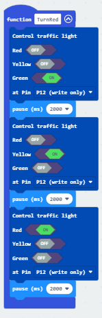
Step 6. Set up a new function (TurnRed)
Control traffic light at P12 green on from SmartCity > Output.
Pause for 2000ms from basic.
Control traffic light at P12 yellow on, pause for 2000ms.
Control traffic light at P12 red on and pause for 2000ms.
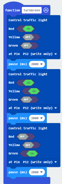
Step 7. Set up a new function (TurnGreen)
Control traffic light at P1 red on from SmartCity > Output.
Pause for 2000ms from basic.
Control traffic light at P1 red and yellow on, pause for 2000ms.
Control traffic light at P1 green on and pause for 2000ms.
Step 8. Set traffic light default status
Insert function TurnGreen to on start.
Step 9. Change traffic light status
Snap if-statement, set received Message ≠ oldmsg to if-condition.
Set oldmsg = receivedMessage (renew the latest traffic status).
Snap another if-statement.
Set receivedMessage = trafficjam to if-condition.
Call function TurnRed.
Set receivedMessage = nojam to else-if-condition.
Call function TurnGreen.
Part 2 Full Solution:
MakeCode: https://makecode.microbit.org/S77055-47262-47956-56848
You could also download the program from the following website:
Part 2 Result
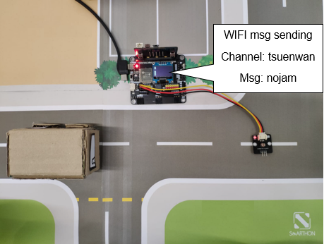
Light sensor is used to detect if there are traffic jam. Once the light intensity is not low, it indicates that there is a traffic jam on the road. Wi-Fi message “nojam” will be sent to another micro:bit (receiver).
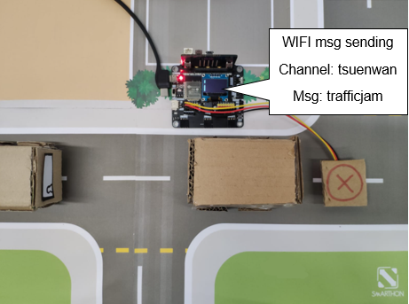
Once the light intensity is too low, it indicates that there is a traffic jam on the road. Wi-Fi message “trafficjam” will be sent to another micro:bit (receiver).
17.7.3. Part 3: Setting up the Smart Street Light (Case 10 Revised)
3.1 Hardware Connect
Connect the white LED Light to P13 port of IoT:bit.
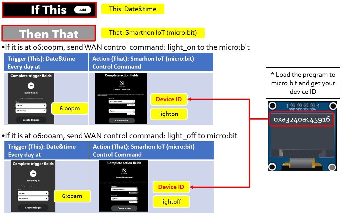
3.2 IOT Setup (IFTTT)
For the setting of IFTTT, please refer to “Chapter 4: Cloud Control micro:bit by IFTTT”
Step 1. Create applet in IFTTT
3.3 Programming (MakeCode)
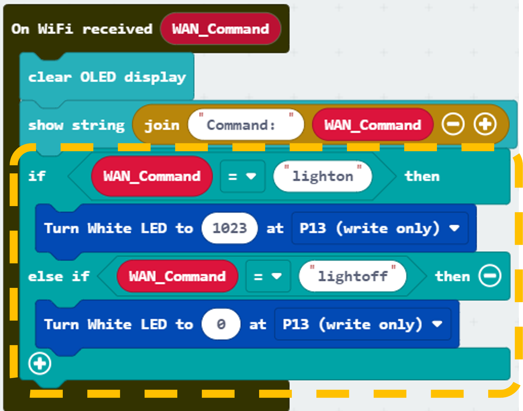
Step 1. Receive WAN command
Go to OLED.
Snap the clear OLED display to On WiFi received to avoid overlap.
Snap the show string to On WiFi received.
Draw the WAN_Command variable to show string placeholder.
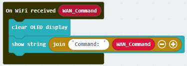
Step 2. Turn on/off LED by WAN command
Snap if-condition.
Set variable WAN_Command = lighton into if-condition.
turn White LED … from SmartCity > Output, turn white LED with intensity: 1023 at P13.
Set variable WAN_Command = lightoff into else-if-condition.
Snap turn White LED … from SmartCity > Output, turn white LED with intensity: 0 at P13.
Part 3 Full Solution:
MakeCode: https://makecode.microbit.org/S35003-46585-93313-79082
You could also download the program from the following website:
Part 3 Result
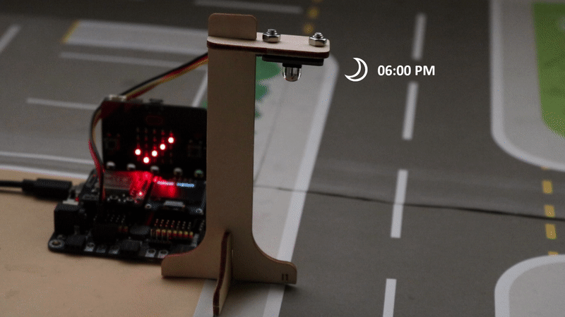
The micro:bit is controlled by IFTTT (trigger by date&time). The LED light will be turned on at 6pm and turned off at 6am every day.
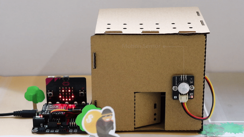
17.7.4. Part 4: Setting up the Smart defense system (Case 7 Revised)
4.1 Hardware Connect
Connect the Motion Sensor to P1 port of IoT:bit.
4.2 IOT Setup (IFTTT)
For the setting of IFTTT, please refer to “Chapter 4: Cloud Control micro:bit by IFTTT”
Step 1
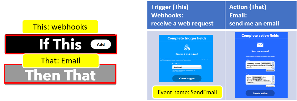
Go to https://ifttt.com , create applet (if webhooks then Email).
Step 2
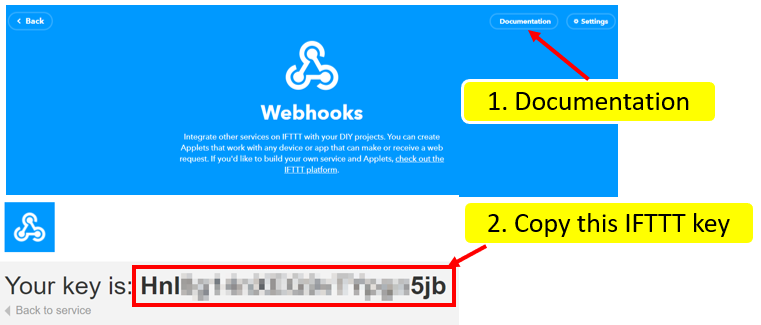
Go to “My services” > “Webhooks”, select “Documentation” . Copy your Webhooks Key as follows:
4.3 Programming (MakeCode)
Step 1. Show Device ID
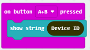
Get on button A+B pressed in Input.
Snap show string and snap Device ID.
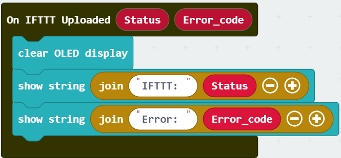
Step 2. Show IFTTT Uploaded Status
Get On IFTTT uploaded from IoT:Bit > IoT:Service.
Snap the clear OLED display to On WiFi received to avoid overlap.
Snap show string inside On IFTTT Uploaded
Draw the variable Status and Error_code to block show string
Step 3. Check motion sensor value
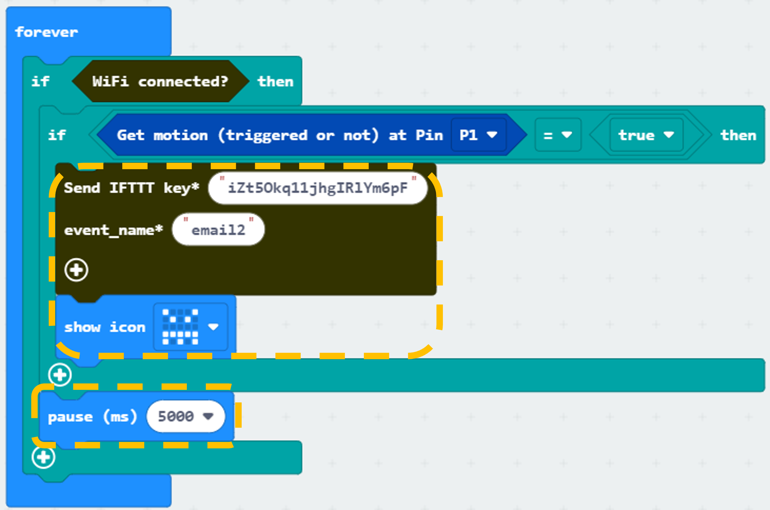
Snap if statement to block forever.
If WiFi is connected,
If get motion (triggered or not) at Pin P1 = true then, that’s say someone is near the door.
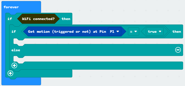
Step 4. Send notification when someone pass by
Snap if statement to block forever.
If WiFi is connected,
Snap Send IFTTT key… from IoT:bit > IoT Services, input your IFTTT key and input event name email2.
Snap show icon from basic and select a monster icon.
Snap Pause after if statement to the loop for 5 seconds delay for checking.
Part 4 Full Solution:
MakeCode: https://makecode.microbit.org/S04257-89623-17473-32946
You could also download the program from the following website:
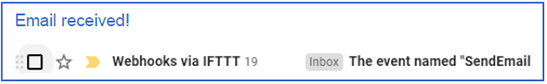
Part 4 Result
When WiFi is connected, if there are any suspicious movement near the door, the buzzer will emit sound and an email will be sent to the house owner. Also, a monster icon will be shown on the micro:bit.
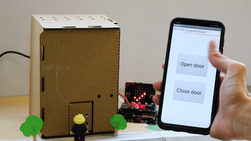
17.7.5. Part 5: Setting up the Smart House door control (Case 9 Revised)
5.1 Hardware Connect
Connect the 180ᵒ Servo to P2 port of IoT:bit.
5.2 IOT Setup (App Inventor)
For more details, please refer to “Chapter 3: Direct control micro:bit by App Inventor 2”
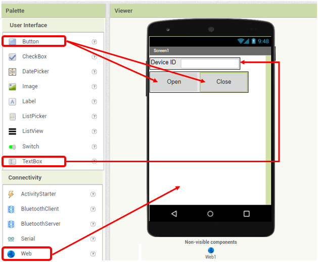
Step 1. Create the page with the components
On Designer:
Drag the components from the left menu – we will need buttons to open or close the door and a textbox for input the Device ID number.
Also, add the invisible component “Web” under connectivity, we will need it for WAN connection
Step 2. Make the programming part
On Blocks:
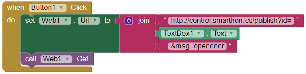
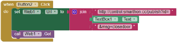
The WAN control command URL is:http://control.smarthon.cc/publish?id=DeviceID&msg=ControlCommand
When Button1 is clicked, it will direct to the URL with given device ID and command “opendoor”.
When Button2 is clicked, it will direct to the URL with given device ID and command “closedoor”.
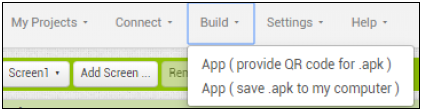
Download the App in your phone to by .apk or scan QR code.
5.3 Programming (MakeCode)
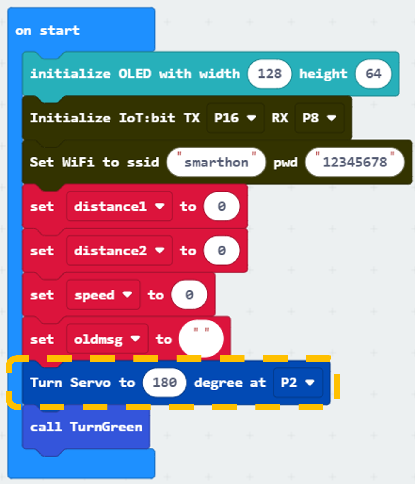
Step 1. Set servo initial position
Snap Turn Servo to … degree from SmartCity > Output
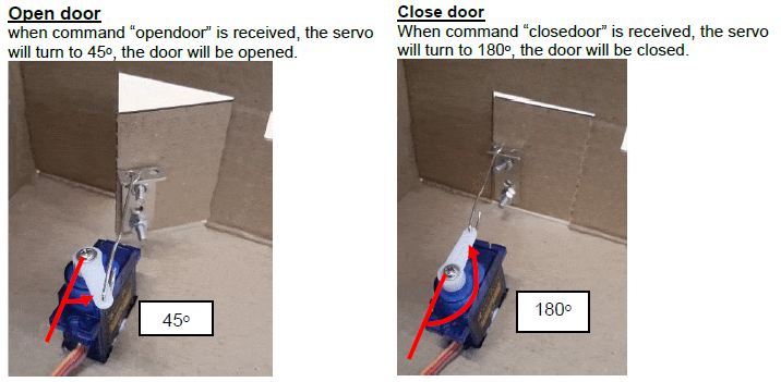
Turn servo to 180 degree at pin P2 (the servo will control the door to be closed initially)
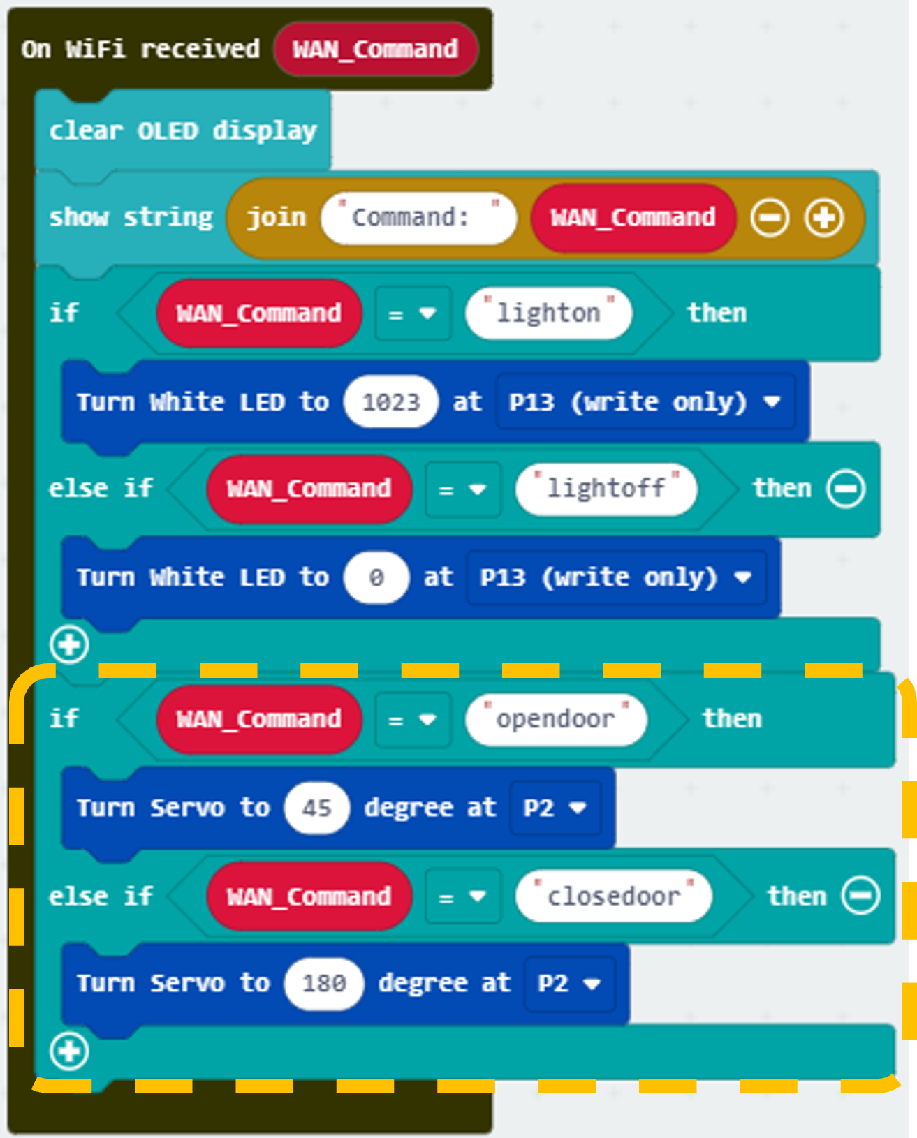
Step 2. Open/close door by WAN command
If WAN command opendoor is received, turn servo to 45 degree at P2 (open door angle) *If WAN command closedoor is received, turn servo to 180 degree at P2 (close door angle)
Part 5 Full Solution:
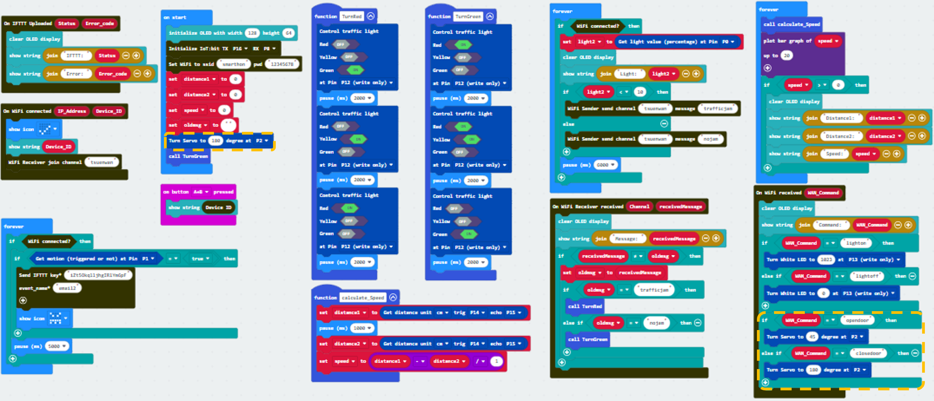
MakeCode: https://makecode.microbit.org/16876-57308-88647-06271
You could also download the program from the following website:
Part 5 Result
Input your device ID number in the textbox, then click button “opendoor” to send command “opendoor”. Click button “Close Door” to send command “closedoor”.
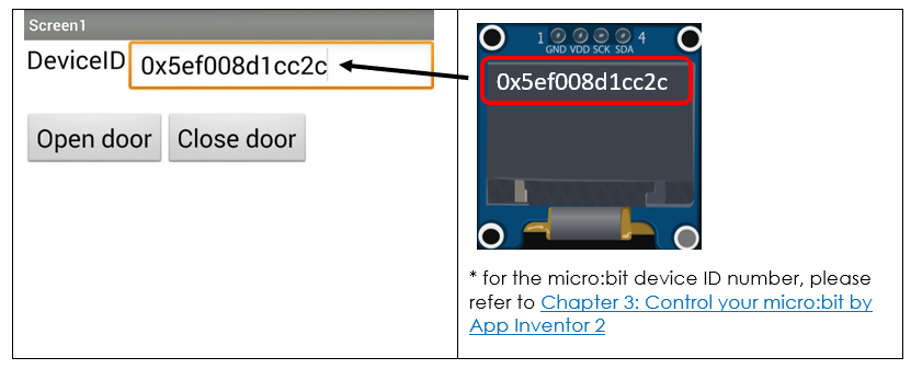
With app inventor and micro:bit, you can control the door open/close by mobile app!